Laser Optics
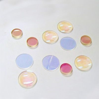
Focus Lens
| Specifications | |
| Material | Zinc Selenide, Ge |
| Design Wavelength | 10.6μm |
| Focal Length Tolerance | ±1% |
| Thickness Tolerance | ±0.1mm |
| Diameter Tolerance | +0.0/-0.1mm |
| Surface Quality | 20-10 |
| Surface Accuracy | λ/2@632.8nm |
| Centration | <3′ |
| Beveling | <0.2×45° |
| Clear Aperture | >90% |
| Coating | AR@10.6um,BR AR@8-14um |
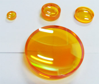
All use CVD Znse, imported from USA. Materials absorption is lower, lens can stand with high power density, and surface is firm, not easy to fall off, resistance to wipe.
Zinc selenide focus lens are widely used in CO2 laser process, including cutting, drilling, carving & other laser system. With the imported material, our products can withstand high power density; and the film is solid, with which the lens are resistant to wipe. Because of the double-side film, the filterability of the light (the wavelength is 10.6μm) can reach 99%.
Reflective Mirror
CO2 Laser Mirror
| Process specifications of laser lens | |
| Material | Gold-plated Silicon, Moly |
| Dimension Tolerance | +0.0/-0.1mm |
| Thickness Tolerance | ±0.1mm |
| Surface Quality | S1:20-10,S2:Fine Ground |
| Surface Accuracy | λ/4@632.8nm |
| Clear Aperture | >90% |
| Parallelism | <1′ |
| Coating | protective film |
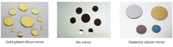
Reflect mirror is one of the most important elements in light transmission system, it can be used as tail mirror and folding mirror in laser cavities, outside the cavities, it plays the role of light-bent machine. Mirrors can be made by various materials.
Mo mirror can be used in harsh environment, also for a long time, can stand high-power and resistant to wipe, but the reflectivity is not so high.
Silicon is used most as the material of mirror, it cost lower, durable, and with stable thermal properties. With gold plated and protection film on the gold, the surface is difficult to be damaged, it also enhance the reflectivity and durable. The fold-plated silicon mirror can stand high –power irradiancy.
Reflect Mirror
Reflect Mirrors mainly material are Molybdenum and silicon. Si is the most common material, its superiority are low cost, strongly Durability and thermal stability. Mo mirror surface is high intensity; it is ideal material which can be applicable to variety of harsh physical environment. Mo mirror usually is uncoating.
| No. | Diameter | Thickness | Incident Light | Material | Coating | ||
| mm | inch | mm | inch | ||||
| MM-20-3 | 20 | 0.79 | 3 | 0.12 | 45 | Molybdenum | None |
| MM-25-3 | 25 | 0.98 | 3 | 0.12 | 45 | Molybdenum | None |
| MM-30-3 | 30 | 1.18 | 3 | 0.12 | 45 | Molybdenum | None |
| MM-38.1-5 | 38.1 | 1.50 | 5 | 0.20 | 46 | Molybdenum | None |
| MM-38.1-6 | 38.1 | 1.50 | 6 | 0.24 | 47 | Molybdenum | None |
| MM-50.8-5 | 50.8 | 2.00 | 5 | 0.20 | 48 | Molybdenum | None |
| MM-50.8-6 | 50.8 | 2.00 | 6 | 0.24 | 49 | Molybdenum | None |
| MM-76.1-6.35 | 76.1 | 3.00 | 6.35 | 0.25 | 50 | Molybdenum | None |
| MM-50.8-7.6 | 76.1 | 3.00 | 7.6 | 0.30 | 51 | Molybdenum | None |
| MM-76.1-10.2 | 76.1 | 3.00 | 10.2 | 0.40 | 52 | Molybdenum | None |
| MM-101.6-10.2 | 101.6 | 4.00 | 10.2 | 0.40 | 53 | Molybdenum | None |
| MS-12-2 | 12 | 0.47 | 2 | 0.08 | 45 | Silicon | Golden & Protection film |
| MS-12.7-2 | 12.7 | 0.50 | 2 | 0.08 | 45 | Silicon | Golden & Protection film |
| MS-13-2 | 13 | 0.51 | 2 | 0.08 | 45 | Silicon | Golden & Protection film |
| MS-15-2 | 15 | 0.59 | 2 | 0.08 | 45 | Silicon | Golden & Protection film |
| MS-15-3 | 15 | 0.59 | 3 | 0.12 | 45 | Silicon | Golden & Protection film |
| MS-16-2 | 16 | 0.63 | 2 | 0.08 | 45 | Silicon | Golden & Protection film |
| MS-16-3 | 16 | 0.63 | 3 | 0.12 | 45 | Silicon | Golden & Protection film |
| MS-19-3 | 19 | 0.75 | 3 | 0.12 | 45 | Silicon | Golden & Protection film |
| MS-20-3 | 20 | 0.79 | 3 | 0.12 | 45 | Silicon | Golden & Protection film |
| MS-25-3 | 25 | 0.98 | 3 | 0.12 | 45 | Silicon | Golden & Protection film |
| MS-25.4-3 | 25.4 | 1.00 | 3 | 0.12 | 45 | Silicon | Golden & Protection film |
| MS-30-3 | 30 | 1.18 | 3 | 0.12 | 45 | Silicon | Golden & Protection film |
| MS-38.1-4 | 38.1 | 1.50 | 4 | 0.16 | 45 | Silicon | Golden & Protection film |
| MS-38.1-5 | 38.1 | 1.50 | 5 | 0.20 | 45 | Silicon | Golden & Protection film |
| MS-38.1-6 | 38.1 | 1.50 | 6 | 0.24 | 45 | Silicon | Golden & Protection film |
| MS-38.1-9 | 38.1 | 1.50 | 9 | 0.35 | 45 | Silicon | Golden & Protection film |
| MS-50-5 | 50 | 1.97 | 5 | 0.20 | 45 | Silicon | Golden & Protection film |
| MS-50.8-5 | 50.8 | 2.00 | 5 | 0.20 | 45 | Silicon | Golden & Protection film |
| MS-50.8-6 | 50.8 | 2.00 | 6 | 0.24 | 45 | Silicon | Golden & Protection film |
| MS-50.8-9 | 50.8 | 2.00 | 9 | 0.35 | 45 | Silicon | Golden & Protection film |
| MS-50.8-10 | 50.8 | 2.00 | 10 | 0.39 | 45 | Silicon | Golden & Protection film |
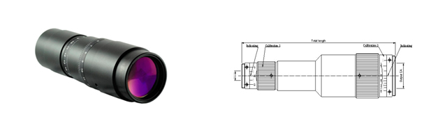
Scan Lens & Beam Expander


CO2 Laser System Scan Lens and Light Expander are widely used in laser marking, engraving, drilling machines, etc.
The Single-chip Flat-field Scanning Mirror has optimized the wide-angle and long focal-length light path, it is widely applied in wide scan range situation.
The absorbability of Zinc Selenide to the infrared wavelengths is low, and can flitter visible light; it is the top choice of beam expander lens.
| Single-Chip CO2 F-Theta Lens | ||||||||
| No. | Material | Scan Scope |
Focal length |
Incident light |
Max. incident light angle |
Dia. of laser beam |
Wavelength | Diameter |
| (mm) | (mm) | (°) | (μm) | (mm) | ||||
| SL-70*70-100-10.6 | ZnSe | 70*70 | 100 | 14 | 30 | 0.15 | 10.6 | 48 |
| SL-110*110-150-10.6 | ZnSe | 110*110 | 150 | 14 | 30 | 0.2 | 10.6 | 48 |
| SL-140*140-200-10.6 | ZnSe | 140*140 | 200 | 14 | 30 | 0.2 | 10.6 | 48 |
| SL-175*175-250-10.6 | ZnSe | 175*175 | 250 | 14 | 30 | 0.25 | 10.6 | 48 |
| SL-210*210-300-10.6 | ZnSe | 210*210 | 300 | 14 | 30 | 0.25 | 10.6 | 48 |
| SL-300*300-430-10.6 | ZnSe | 300*300 | 430 | 16 | 20 | 0.3 | 10.6 | 48 |
| SL-400*400-590-10.6 | ZnSe | 400*400 | 590 | 16 | 20 | 0.35 | 10.6 | 48 |
| SL-500*500-623-10.6 | ZnSe | 500*500 | 623 | 16 | 22 | 0.4 | 10.6 | 48 |
| SL-600*600-700-10.6 | ZnSe | 600*600 | 700 | 16 | 20 | 0.45 | 10.6 | 48 |
| SL-300*300-450-10.6-D65 | ZnSe | 300*300 | 450 | 28 | 20 | 0.35 | 10.6 | 65 |
| SL-400*400-545-10.6-D65 | ZnSe | 400*400 | 545 | 28 | 20 | 0.4 | 10.6 | 65 |
| SL-500*500-716-10.6-D65 | ZnSe | 500*500 | 716 | 28 | 22 | 0.4 | 10.6 | 65 |
| SL-35*35-100-10.6-D32 | ZnSe | 35*35 | 100 | 10 | 11 | 0.12 | 10.6 | 32 |
| SL-50*50-100-10.6-D32 | ZnSe | 50*50 | 100 | 10 | 15 | 0.12 | 10.6 | 32 |
| Beam Expander | |||||||
| Part Number | Material | Magnification | Dia (mm) |
Length (mm) |
Input CA (mm) |
Output CA (mm) |
Connect |
| EX-2X-10.6 | ZnSe | 2 | 22 | 35 | 15 | 17 | M22*0.75 |
| EX-2.5-10.6 | ZnSe | 2.5 | 37 | 60 | 13.5 | 30 | M22*0.75 |
| EX-3X-10.6 | ZnSe | 3 | 22 | 62 | 10 | 15 | M22*0.75 |
| EX-4X-10.6 | ZnSe | 4 | 27 | 70 | 10 | 20 | M22*0.75 |
| EX-5X-10.6 | ZnSe | 5 | 30 | 72 | 10 | 23 | M22*0.75 |
| EX-6X-10.6 | ZnSe | 6 | 36 | 75 | 10 | 30 | M22*0.75 |
| EX-8X-10.6 | ZnSe | 8 | 36 | 73 | 10 | 30 | M22*0.75 |
| Special Size | |||||||
| EX-0.5X-10.6 | ZnSe | 0.5 | 25 | 36.35 | 10.8 | 10.8 | M22*0.75 |
| EX-0.5X-10.6 | ZnSe | 1.2 | 25 | 30.69 | 13.1 | 13.1 | M22*0.75 |
| EX-0.5X-10.6 | ZnSe | 3.5 | 40 | 53.26 | 13.6 | 33 | M22*0.75 |
Beam Combiner

Beam combiner combines the outputs of multiple laser sources (often in the form of laser arrays) to obtain a single output beam. The use of a scalable beam-combiner leads to a power-scalable laser source, even if the single lasers are not scalable.
| Part Number | Diameter | Thickness | Material | Coating | ||
| mm | inch | mm | inch | |||
| W-10.6-25.4-3 | 25.4 | 1.000 | 3 | 0.118 | Znse | side 1:AR@10.6um,side 2:HR@500-700nm |
| W-10.6-30-3 | 30 | 1.181 | 3 | 0.118 | Znse | side 1:AR@10.6um,side 2:HR@500-700nm |
| W-10.6-38.1-4 | 38.1 | 1.500 | 4 | 0.157 | Znse | side 1:AR@10.6um,side 2:HR@500-700nm |
| W-10.6-38.1-5 | 38.1 | 1.500 | 5 | 0.197 | Znse | side 1:AR@10.6um,side 2:HR@500-700nm |
| W-10.6-50.8-4 | 50.8 | 2.000 | 4 | 0.157 | Znse | side 1:AR@10.6um,side 2:HR@500-700nm |
| W-10.6-63.5-5 | 63.5 | 2.500 | 5 | 0.197 | Znse | side 1:AR@10.6um,side 2:HR@500-700nm |
| W-10.6-75-9 | 75 | 2.953 | 9 | 0.354 | Znse | side 1:AR@10.6um,side 2:HR@500-700nm |
| W-10.6-25.4-3 | 25.4 | 1.000 | 3 | 0.118 | Znse | side 1:AR@10.6um,side 2:HR@650nm |
| W-10.6-30-3 | 30 | 1.181 | 3 | 0.118 | Znse | side 1:AR@10.6um,side 2:HR@650nm |
| W-10.6-38.1-4 | 38.1 | 1.500 | 4 | 0.157 | Znse | side 1:AR@10.6um,side 2:HR@650nm |
| W-10.6-38.1-5 | 38.1 | 1.500 | 5 | 0.197 | Znse | side 1:AR@10.6um,side 2:HR@650nm |
| W-10.6-50.8-4 | 50.8 | 2.000 | 4 | 0.157 | Znse | side 1:AR@10.6um,side 2:HR@650nm |
| W-10.6-63.5-5 | 63.5 | 2.500 | 5 | 0.197 | Znse | side 1:AR@10.6um,side 2:HR@650nm |
| W-10.6-75-9 | 75 | 2.953 | 9 | 0.354 | Znse | side 1:AR@10.6um,side 2:HR@650nm |
Beam Splitter

Beam Splitters can make part of the light through the lens. and reflects the remaining light. The main application is bisected laser light to the ratio of 50 : 50 Common Beam Splitters is used to separate or merge the laser beam. The polarized beam splitters are used to split or merge the two orthogonal polarization States of the laser beam. The beam splitter performance major determinant of its coating properties.
Output Couple & Rear Mirror
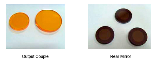
Output couple and rear mirror are the most important elements of laser tube. The combination use of these two makes the laser beam available, the material of OC is Znse and RM is silicon.
| Output Couple | ||||||
| No. | Diameter | Thickness | Transmission% | Material | ||
| mm | inch | mm | inch | |||
| OC–20 20 | 20 | 0.7874 | 3 | 0.118 | 20 | ZnSe(USA) |
| OC–20 25 | 20 | 0.7874 | 3 | 0.118 | 25 | ZnSe(USA) |
| OC–20 30 | 20 | 0.7874 | 3 | 0.118 | 30 | ZnSe(USA) |
| OC–20 35 | 20 | 0.7874 | 3 | 0.118 | 35 | ZnSe(USA) |
| OC–25 20 | 25 | 0.98425 | 3 | 0.118 | 20 | ZnSe(USA) |
| OC–25 25 | 25 | 0.98425 | 3 | 0.118 | 25 | ZnSe(USA) |
| OC–25 30 | 25 | 0.98425 | 3 | 0.118 | 30 | ZnSe(USA) |
| OC–25 35 | 25 | 0.98425 | 3 | 0.118 | 35 | ZnSe(USA) |
| OC–30 20 | 30 | 1.1811 | 3 | 0.118 | 20 | ZnSe(USA) |
| OC–30 25 | 30 | 1.1811 | 3 | 0.118 | 25 | ZnSe(USA) |
| OC–30 30 | 30 | 1.1811 | 3 | 0.118 | 30 | ZnSe(USA) |
| OC–30 35 | 30 | 1.1811 | 3 | 0.118 | 35 | ZnSe(USA) |
| Rear Mirror | ||||||
| No. | Diameter | Thickness | Radius (meter) |
material | ||
| mm | inch | mm | inch | |||
| RM-20 3 RM-20 4 RM-20 5 |
20 | 0.79 | 3 | 0.12 | 3 4 5 |
silicon |
| RM-25 3 RM-25 4 RM-25 5 |
25 | 0.98 | 3 | 0.12 | 3 4 5 |
silicon |
| RM-30 3 RM-30 4 RM-30 5 |
30 | 1.18 | 3 | 0.12 | 3 4 5 |
silicon |
High Power
High power CO2 laser assembly
Wholesale imported USA focus lens, Phase Retarder, Phase Shifter, nozzles, for Amada, Bystronic, Cincinnati, Mazak, Mitsubishi, Trumpf, etc. The following is a simply list
Infrared Processing
Infrared Lens

| Material | Zinc Selenide,Ge |
| Diameter Tolerance | +0.0/-0.1mm |
| Focal Length Tolerance | ±1% |
| Thickness Tolerance | ±0.2mm |
| Design Wavelength | 10.6μm | Surface Accuracy | λ/2@632.8nm |
| Surface Quality | 20-10 |
| Bevelling | < 0.2 × 45° |
| Clear Aperture | >90% |
| Centration | < 3' |
| Coating | AR@10.6um,BR AR@8-14um |
Prism
Prisms & Rhombs

| Material | Zinc selenide |
| Angular Tolerance | ±3' |
| Dimension Tolerance | Tolerance:±0.1mm |
| Surface Accuracy | λ/10@632.8nm |
| Surface Quality | 20-10 |
| Beveling | <0.2×45° |
| Clear Aperture | >90% |
| Coating | Custom Design |
Windows
| Material | Zinc Selenide |
| Thickness Tolerance | ±0.1mm |
| Diameter Tolerance | +0.0/-0.1mm |
| Surface Quality | 20-10 |
| Surface Accuracy | λ/4@632.8nm |
| Parallelism | <1′ |
| Bevelling | <0.2×45° |
| Clear Aperture | >90% |
| Coating | Custom Design |
YAG Laser Assembly
YAG lens
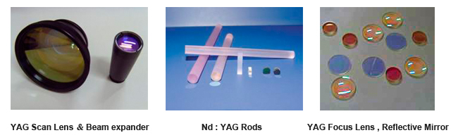
YAG laser has been widely used in material processing, such as cutting, drilling, welding, etc, which not only improves the quality of the work pieces, but also the work efficiency. With Nd: YAG crystal’s excellent thermal performance, the laser’s reliability, efficiency, and power has been enhanced a lot. So it is widely used in laser rangefinder, laser radar, laser industrial processing, laser medical fields, etc. Besides that, it also provides a quick and precious method for scientific research.
YAG scan lens
| Part No. | Focal Length (mm) F | Working Distance (mm) S | Scan Field [mm²] | Angle of Incidence θ max | Diameter of Incident Light Ø [mm] | Diameter of Gaussian Dispersion Flare [µm] | Best Position m1/m2 [mm] | Screwed Joint |
| F-Theta scan lens λ=1064nm | ||||||||
| SL-30-63-355 | 63 | 59 | 30 × 30 | ±18º | 6 | 10 | 10/10 | M39 x 1 |
| SL-110-160-355 | 160 | 174 | 110 × 110 | ±28º | 7 | 15 | 16/16 | M85 x 1 |
| F-Theta scan lens λ=532nm | ||||||||
| SL-70-100-532 | 100 | 111 | 70 × 70 | ±28º | 12 | 10 | 16/16 | M85 x 1 |
| SL-110-160-532 | 160 | 180 | 110 × 110 | ±28º | 12 | 16 | 16/16 | M85x1 |
| F-Theta scan lens λ=1064nm | ||||||||
| SL-40-63-1064-12 | 63 | 59 | 40 × 40 | ±25º | 12 | 10 | 16/16 | M85 x 1 |
| SL-70-100-1064-12 | 100 | 111 | 70 × 70 | ±28º | 12 | 16 | 16/16 | M85 x 1 |
| SL-110-160-1064-12 | 160 | 176 | 110 × 110 | ±28º | 12 | 26 | 16/16 | M85 x 1 |
| SL-150-210-1064-12 | 210 | 230 | 150 x 150 | ±28º | 12 | 34 | 16/16 | M85 x 1 |
| SL-175-254-1064-12 | 254 | 280 | 175 × 175 | ±28º | 16 | 31 | 16/16 | M85 x 1 |
| SL-200-290-1064-12 | 290 | 300 | 200 × 200 | ±28º | 16 | 34 | 16/16 | M85 x 1 |
| SL-220-330-1064-12 | 330 | 346 | 220 × 220 | ±28º | 16 | 40 | 16/16 | M85 x 1 |
| F-Theta scan lens λ=1064nm | ||||||||
| SL-110-163-1064-20 | 163 | 185 | 110X110 | ±28º | 20 | 17 | 18/24 | M85x1 |
| SL-145-210-1064-20 | 210 | 232 | 145×145 | ±28º | 20 | 24 | 18/24 | M85x1 |
| SL-175-254-1064-20 | 254 | 257 | 175×175 | ±28º | 20 | 31 | 18/24 | M85x1 |
| SL-300-420-1064-20 | 420 | 456 | 300×300 | ±28º | 20 | 55 | 18/24 | M85x1 |
| SL-400-650-1064-20 | 650 | 697 | 400×400 | ±28º | 20 | 85 | 18/24 | M85x1 |
YAG Beam Expander
| Part Number | Material | Magnification | Dia(mm) | Length(mm) | InputCA(mm) | OutputCA(mm) | Screwed joint |
| YAG Beam Expander=532nm | |||||||
| EX-2X-532 | Glass | 2 | 22 | 51 | 10 | 14 | M22 x 0.75 |
| EX-2.5X-532 | Glass | 2.5 | 22 | 51 | 10 | 14 | M22 x 0.75 |
| EX-3X-532 | Glass | 3 | 25 | 68 | 10 | 18 | M22 x 0.75 |
| EX-4X-532 | Glass | 4 | 31 | 75 | 10 | 24 | M22 x 0.75 |
| EX-5X-532 | Glass | 5 | 33 | 73 | 10 | 26 | M22 x 0.75 |
| EX-6X-532 | Glass | 6 | 38 | 75 | 10 | 28 | M22 x 0.75 |
| EX-8X-532 | Glass | 8 | 45 | 77 | 10 | 29 | M22 x 0.75 |
| YAG Beam Expander,λ=532nm | |||||||
| EX-10X-532 | Quartz | 10 | 14 | 51 | 10 | 18 | M22 x 0.75 |
| EX-15X-532 | Quartz | 15 | 14 | 51 | 10 | 18 | M22 x 0.75 |
| EX-20X-532 | Quartz | 20 | 14 | 68 | 10 | 20 | M22 x 0.75 |
| YAG Beam Expander,λ=1064nm | |||||||
| EX-2X-1064 | Glass | 2 | 22 | 51 | 10 | 14 | M22 x 0.75 |
| EX-2.5X-1064 | Glass | 2.5 | 22 | 51 | 10 | 14 | M22 x 0.75 |
| EX-3X-1064 | Glass | 3 | 25 | 68 | 10 | 18 | M22 x 0.75 |
| EX-4X-1064 | Glass | 4 | 31 | 75 | 10 | 24 | M22 x 0.75 |
| EX-5X-1064 | Glass | 5 | 33 | 73 | 10 | 26 | M22 x 0.75 |
| EX-6X-1064 | Glass | 6 | 38 | 75 | 10 | 28 | M22 x 0.75 |
| EX-8X-1064 | Glass | 8 | 45 | 77 | 10 | 29 | M22 x 0.75 |
YAG : Total Reflective Mirror
YAG : Reflection Mirror
| Part Number | Name | Spec. |
| YAG Marking Machine Component | ||
| RM-D20-T5 | Total reflection mirror | ¢20X5 |
| PM-D20-Tr15 | Partial reflection mirror | ¢20X5 T=15﹪ |
| PM-D20-Tr20 | Partial reflection mirror | ¢20X5 20﹪ |
| PM-D20-Tr12 | Partial reflection mirror | ¢20X5 12﹪ |
| BM-D20-T3 | Beam combiner | ¢20X3 (HR@λ=632.8,AR@λ=1064) |
| YAG Welding Machine Component | ||
| RM-D20-T5 | Total reflection mirror | ¢20X5 |
| PM-D20-T6-Tr40 | Partial reflection mirror | ¢20X6 T=40﹪ |
| 45 RM-D45-T5 | 45°reflection mirror | ¢45*5 |
| 45 RM-D45-T3 | 45°reflection mirror | ¢45*3 |
| PW-D40 | Protective window | ¢40 |
| PW-D48 | Protective window | ¢48 |
YAG : Half Reflective Mirror
YAG : Partial Reflection Mirror

| Part number | Name | Spec. |
| YAG Marking Machine Component | ||
| PM-D20-Tr12 | Partial reflection mirror | ¢20X5 12﹪ |
| PM-D20-Tr15 | Partial reflection mirror | ¢20X5 T=15﹪ |
| PM-D20-Tr20 | Partial reflection mirror | ¢20X5 20﹪ |
| YAG welding machine component | ||
| PM-D20-T6-Tr40 | Partial reflection mirror | ¢20X6 T=40﹪ |
Rods
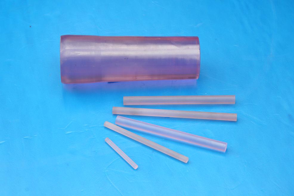
In all laser equipment laser rod acts as a very important role. Whether in industrial, medical laser equipment or military laser equipment. Laser rods play a very important role.
Nd: YAG is cubic crystal, it is isotropic crystal. Nd: YAG is a four-level system, high quantum efficiency, broad stimulated emission area, so the threshold is much lower than ruby and neodymium glass. Also, because the Nd: YAG crystal has excellent thermal properties, it is ideal crystal for continuous and heavy-frequency devices. Nd: YAG crystal is able to work continuously at room temperature, the only solid working substances in low and medium-power pulse devices, the current application of Nd: YAG is much more broader than any other substances.
Nd: YAG ROD is the most mature and widely used as solid-state laser material, adopted by R&D, medical, industrial and military customers. Its main and obvious advantages are: high gain, low threshold, high efficiency, low loss at 1.064 μm, as well as high optical quality, good thermal conductivity and thermal shock characteristics, stable chemical and mechanical properties, which make Nd: YAG as the most suitable and commercial laser material for various modes of operation (CW, pulsed, Q-switched, mode locked and cavity dumped).
Parameters
| Dopant concentration, at.% | 0.5-1.2 at% |
| Flatness | < λ/10(@632.8nm) |
| Orientation | <111> ± 5° or <100> ± 5° |
| Parallelism | ≤ 10" |
| Perpendicularity | ≤ 5' |
| Used for | 1064nm pulse/CW solid lasers |
| Dimensional tolerances | Diameter: ±0.05mm Length: ±0.5mm Chamfer: 0.07+0.005/-0.00″ at 45° |
| Optical Quality | Interference fringes ≤ 0. 25 λ /inch Extinction ration Ф3-Ф6.35 ≥ 28dB Ф7-Ф10 ≥ 25dB |
| AR Coating Reflectivity | ≤ 0.2% (@1064nm) |
| HR-Coating Reflectivity | >99.8%@1064nm and R<5%@808nm |
| Parameters of lasers | Point efficiency of long pulse:3.3%(lamp pumped,20j input), slope efficiency of long pulse 4.2% |
Dimension
The most commonly used size of the ND: YAG laser rod diameter Is from1.5mm to 18.0mm, 0.5mm up by ladder. Length size
from 15mm, 20mm, 25mm, 30mm, 35mm, 40mm, 45mm, 50mm, 55mm, 60mm, 70mm to 200mm.
we can use diameter and length as a combination of the size.
Here is the most common size of Nd:YAG Rods:
| Part number | Diameter(mm) | Length(mm) | State of product | Applied machine |
| Rod-D3-L50 | 3 | 50 | ||
| Rod-D3-L60 | 3 | 60 | ||
| Rod-D3-L110 | 3 | 110 | ||
| Rod-D3-L120 | 3 | 120 | Always have stock | Laser making machine |
| Rod-D4-L50 | 4 | 50 | ||
| Rod-D4-L60 | 4 | 60 | ||
| Rod-D4-L120 | 4 | 120 | Always have stock | Laser making machine |
| Rod-D4-L130 | 4 | 130 | Always have stock | Laser making machine |
| Rod-D5-L110 | 5 | 110 | ||
| Rod-D5-L120 | 5 | 120 | Always have stock | Laser making machine |
| Rod-D5-L140 | 5 | 140 | ||
| Rod-D6-L110 | 6 | 110 | ||
| Rod-D6-L150 | 6 | 150 | ||
| Rod-D8-L147 | 8 | 147 | Always have stock | Laser making machine |
| Rod-D8-L180 | 8 | 180 |
 - Mr Shailesh Rao